


By:Dustin Hoaglin
MADE TO MEASURE NEWS | VECTORSEDU | August 2023
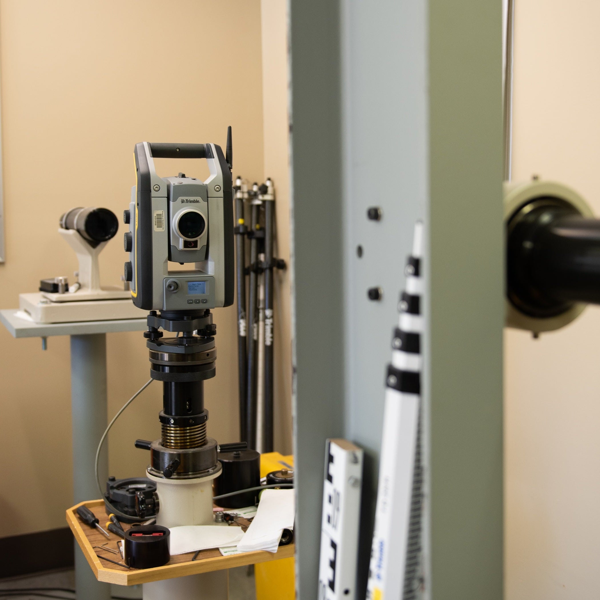
Trimble R12i and R10 vs. R8s - What you need to know!
Over the past few weeks, I've gained valuable insights into the operational nuances of Trimble's contemporary R12i, R12, and R10 receivers. This includes understanding the distinctions between what users encounter in TBC, compared to the functionality of the older Trimble R8s or R6 receiver systems.
Peeling back the veil and demystifying some aspects can enhance our comprehension of why the R12i holds such impressive capabilities in contrast. This deep dive into comparing the old vs new receivers will also give us a glimpse into the constraints of the R12i, now that technological advancements have taken place.
In the existing TBC configuration, there is no alert raised for a poor single RTK vector if accepted (Force Stored) in the field. Do I believe that incorporating a function to signal or flag such single vector checks would be advantageous? Absolutely! At present, users only receive a notification if a point possesses two values (Point Tolerance) or if a point has a meaned (dual) vector tolerance (GNSS Vector).
Point Tolerance

GNSS Vector (Meaned)

Understanding the way R8/R6s receivers process vectors vs. the way a modern R12i/R12/R10 receiver does will allow us to make better decisions.
Under the previous R8 approach, users could either attain a Fixed or a Float solution. However, with the advent of the R10, this distinction vanished, and the field crew now determines if a point meets the required accuracy. While I will revisit this and delve into Quality Assurance/Quality Control practices later, let's look at some sample data to see what's happening.
Comparing the data collector screens of older and newer receivers reveals a contrast. Specifically, the older R8s exhibit "RTK: Fixed" and display the RMS value, a feature absent in the modern R10/R12 receivers.

A field crew was on this point for almost 15 minutes. It should have been clear to them at that point that the receiver was having a problem collecting the shot. My guess would be electromagnetic interference from a microwave or cell tower etc.


Note that the field crew was only getting 8 satellites, even though the point was situated in an open area without obstructions like trees or buildings. The absence of epochs implies that not one reading in the 15 minutes met the criteria for being considered a valid epoch based on the standards set up in the survey style (typically 0.08’). Both shots on the south side of the project only have 8 satellites. A few minutes later, in the same data set, as the crew moved northwards and potentially away from any interference sources, they gained access to 15 satellites. Using an R10 or R12, crews should have 10 to 20 satellites. This number can increase to as many as 30 if they are using an R12 base to R12 rover setup.

Even after 15 minutes, the solution on the data collector remained at +/- 2.2H and 3.5V. When the crew chose to Force Store the point, a warning would have appeared up in the field, asking, “Are you sure you want to store this?” Despite the warning, they proceeded to accept and store the point. This is why TBC did not flag the poor single RTK vector. The field crew acknowledged that what they had captured was satisfactory for this shot.


This R12i receiver is also tilted at a 41° angle, adding a computation error to the solution in addition to the GNSS solution error. The precision displayed on the data collector screen shows the current solution, including both RTK and IMU (Inertial Measurement Unit) contributions. In other words, there is a GNSS solution that is +/- something (RTK), and on top of that, the more tilt, the more error the IMU introduces. Trimble advises against tilting beyond 30°. However, a user can tilt as much as they would like, and the error is reflected in the number at the top of the data collector (RTK+IMU) and then double-checked before storing.
Once more, the reason this issue is not flagged in TBC is because the field crew said this was ok for this shot.
Now let’s compare the R10/R12 with the R8/R6.
R8/R6 -The red circles in the below graphic indicate all possible solutions for the point. The R8 receiver would come up with the best solution after two or three minutes of data collection (Fixed). It would retain that one solution and use the average of the crossing solutions (paths or waves) to calculate an RMS value (blue circle). The data collector and TBC will flag high RMS values.
The below example shows only three satellites. In your mind, expand this to 8 or 10 satellites. Also, consider this not just in a 2D context but in 3D as well.

R10/R12 -These receivers don't calculate or display RMS because they retain multiple solutions. R10/R12 receivers hold onto every solution, and time is your friend. The longer you track, the better the results. (Avoid flipping the receiver or turning it upside down—this is detrimental to both the R10 and R12 series receivers.) By holding onto every possible solution R10/R12 devices create an error ellipse (depicted in green in the below graphic). If the ellipse is small enough for the precision sought (typically 0.08'), the point is automatically stored. If the ellipse is larger, the data collector will keep collecting (forever) until it becomes smaller or until the field crew forces the shot or cancels the shot. If the point is force stored, the data collector will ask if those numbers (X_H to X_V) are ok. If the user confirms this is ok, there will be no flag in TBC.
The below example also shows only three satellites. In your mind, expand this to 15 or 30 satellites. Consider this not just in 2D but in 3D. This is why the R12 works so well under a canopy and next to buildings.
R10/R12 receivers remember where the old solutions previously have been calculated. This is why dumping them or turning them over is bad. I suspect that even throwing the R10/R12 in the back of a truck and driving from point to point can introduce noise into solution memory. My field workflow solution recommendation is outlined a bit later in this article.

Once field collection is complete, QA/QC the data in TBC:
- Bring in your data and open the vector spreadsheet.
- Sort by the V. Precision column.
- Review data for rogue shots.
Even with a sizable 2000 points collected, you can rapidly (within seconds) check for any outlier shots where the field crew made errors. Sorting by Epoch and Tilt Distance is also possible.

Now, as promised, my field workflow solution follows Trimble's new recommendations. Turning the receiver over will not work!
Reset RTK and reset SV Tracking. They do different things.

From the Trimble Access Help Portal:

The idea here is if you want to verify you have a good solution installation after storing an important point you should use “Reset SV tracking”. This action prompts the R10/R12 to initiate a completely fresh start, similar to the approach employed with older receivers by flipping them over.
I also believe it's beneficial to apply "Reset SV tracking" every time you pull the R10/R12 out of the truck. This helps eliminate any junk data that it may have picked up in transit to the next point. However, note the warning from the Trimble Access help portal (image above). This action shouldn't be performed in a "compromised GNSS environment", such as in close proximity to trees or buildings. Only perform “Reset SV tracking” when there is a wide-open sky! "Reset RTK” is for use when you ARE in a "compromised GNSS environment".
When arriving at the measurement point, the field crew should:
- Assess potential obstacles like trees or buildings.
- Remove the R10/R12 from the vehicle.
- Walk the rover to the best open sky area near the point to be measured.
- Use the "Reset SV tracking" option, allowing 30 seconds to 1 minute for the precision values to stabilize.
- If the values don’t come down it indicates an issue, and the crew may need to return later with a different satellite constellation.
After achieving improved precision in the open sky, the field crew may proceed to the measurement point:
- Place the rover on the point and wait another 30 seconds to 1 minute for the precision values to reduce again after entering the “compromised GNSS environment”.
- Measure the point, and with the rod tip remaining on the point, use the "Reset RTK" option.
- Allow the R10/R12 to check the solution previously obtained. Wait 30 seconds to a minute for the precisions to reduce again.
- Measure the point a second time.
- Store the measurement to confirm successful operation in the compromised environment.
Now, let's delve into the IMU and the tilt factor. The IMU prefers motion and doesn’t like to be held still. So, for optimal IMU performance, a bit of movement is key. This is why you need to "stir the soup" or walk around with the rod to get the IMU into action. However, if you are holding it very plum and/or still the IMU will not operate at its best. This is precisely why Trimble has the IMU automatically turn off when you go into measure control point mode.
Remember, IMUs inherently introduce some random errors that change constantly and may increase when held still. So, the bottom line is to leverage the IMU when it's necessary but refrain from doing so when not needed, especially for crucial shots. If you find yourself needing to tilt for an important shot, take extra steps to ensure that you're securing an accurate measurement.
Dustin Hoaglin, PLS is a Trimble Certified Trainer, Regional Manager, and TBC Power User for Vectors Inc. and is based in Albuquerque, New Mexico.
©Vectors Inc.